High-deposition welding is not simply a matter of turning up amperage: usable output depends on wire-feed continuity, deposition efficiency, weld position, slag handling and the shielding method. By the end, you will be able to compare FCAW with SMAW, GMAW and submerged arc welding, then match a wire classification and setup to the joint, base metal and work environment.
Key takeaways
- Use continuous wire feeding to reduce electrode-change interruptions.
- Choose gas-shielded or self-shielded FCAW based on the production problem.
- Select the classification before matching wire diameter to the joint.
- Keep feeder and arc settings within the wire’s qualified operating range.
How flux-cored wire puts more usable weld metal into the joint
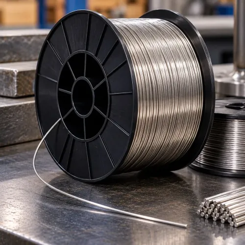
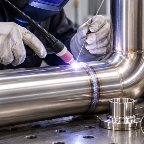
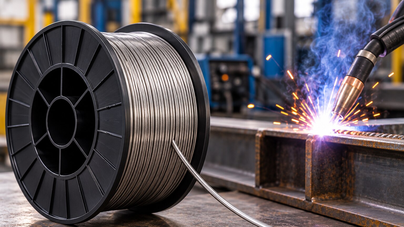
FCAW puts more usable weld metal into a joint through continuous wire feeding, high wire-feed speeds and fewer interruptions for electrode changes. Its flux core stabilises the arc, forms protective slag and shapes the molten pool; gas-shielded wire adds external shielding, while self-shielded wire generates shielding from the core.
The result is a high FCAW deposition rate and a usable weld-metal fraction reflected in deposition efficiency 80–90% versus 55–65% for covered electrodes.
| Process | Output advantage | Limitation |
|---|---|---|
| Flux-cored arc welding | Continuous feeding, high deposition and longer arc-on time | Slag removal, fumes and position limits can reduce the time saving |
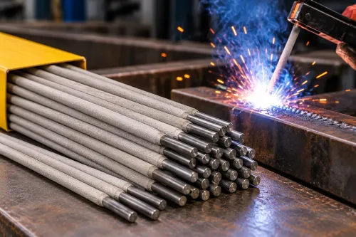
| SMAW | Simple equipment and good access for repairs | Stop-start work, electrode stubs and frequent changes reduce arc-on time |
| GMAW/MIG | Continuous wire with no slag removal | More sensitive to wind; solid wire does not provide FCAW’s flux-based pool control |
| Submerged arc welding | Very high deposition for long, accessible flat or horizontal welds | Requires specialised equipment and is unsuitable for many positions and exposed joints |
Compare processes using both kilograms deposited per hour and the time required to finish an acceptable weld. A large FCAW wire can deposit rapidly in a flat groove or horizontal fillet, but its pool and slag system can restrict vertical-up or overhead work. Smaller all-position wire lowers deposition capacity.
Cleaning between passes, repositioning, wire changes, fume control and inspection can erase the apparent advantage, so compare complete weld cycles—not deposition rate alone.
Gas-shielded and self-shielded FCAW solve different production problems
Choose gas-shielded FCAW when you have a stable work area, shielding-gas equipment and enough draft protection to preserve the gas envelope. It generally gives higher deposition, a more controllable arc and easier fume control than self-shielded FCAW.
Gas composition changes arc behaviour, penetration, spatter and bead shape. Use the wire classification and qualified welding procedure to select an argon/CO₂ mixture versus 100% CO₂; choosing the cheapest gas can create porosity or move the weld outside its qualified range.
| Option | Strength | Choose it when |
|---|---|---|
| Gas-shielded FCAW | Higher deposition and controlled arc with external shielding gas | Indoor fabrication, large fillets and long welds where DCEP, gas flow and draft control are available |
| Self-shielded FCAW | Flux generates the shielding gases; no cylinder or hose required | Outdoor welding, repair work and remote jobs where portability matters and wind protection is limited |
Self-shielded FCAW is not windproof. Excessive air movement can disturb its flux-generated gas envelope and cause porosity, while gas-shielded FCAW loses protection even more readily when drafts dilute or displace shielding gas.
Check polarity before loading the wire: many gas-shielded products use DCEP, while several self-shielded products use DCEN. Reversing it can cause spatter, poor penetration and an unstable arc. Also compare the slag system, because it supports the pool, shapes the bead and determines positional behaviour; slag removal remains part of the production time.
Where high-deposition FCAW delivers its biggest time advantage
The biggest time advantage appears in flat welding and horizontal fillet welds, especially large fillet welds on long, accessible runs. Large-diameter wire and high wire-feed speed support high deposition while the operator maintains travel speed without frequent repositioning.
| Position or joint | Why FCAW saves time | What limits the advantage |
|---|---|---|
| Flat welding | Uses the highest practical wire-feed rates for large fillet welds, groove welds and multi-pass welds | High heat input can increase distortion and require restraint or balanced sequencing |
| Horizontal fillet welds | Keeps a large, supported weld pool on continuous structural joints | Excessive leg size can slow travel speed and raise interpass temperature |
| Vertical-up welding | An all-position wire controls the pool and supports uphill passes where access prevents repositioning | Smaller wire and lower deposition rates are normally needed |
| Overhead welding | An all-position wire allows welding without turning the workpiece | Lower settings, careful slag removal and slower travel reduce the headline deposition rate |
Multi-pass groove welds reward FCAW when the joint remains accessible for consistent passes. After every pass, complete interpass cleaning and inspect the weld toes and groove corners; trapped slag in either location can force gouging and repair, erasing the deposition-time gain.
A high-deposition procedure is not automatically the fastest cycle. Account for heat input, distortion control, interpass temperature checks, slag removal and access before choosing a large wire; vertical-up welding or overhead welding with an all-position wire can finish sooner when it avoids repositioning and rework.
Choose the classification before you choose the wire diameter
A 1.2 mm wire is the wrong choice if its classification does not match the base metal, weld strength and service conditions. Read the complete classification suffix in the AWS filler-metal specification before selecting diameter: it identifies tensile-strength class, impact requirements, polarity, recommended shielding gas, position capability and, where stated, low-hydrogen H4 or H8 performance.
Check these points on the certificate and product label:
- Match the base-metal grade and required tensile strength; carbon-steel E71T-1 is not a substitute for a stainless filler.
- Confirm impact requirements at the specified test temperature. A wire that meets strength but fails toughness can invalidate the procedure.
- Match polarity exactly. A wire designed for DCEP is not automatically suitable for DCEN or AC.
- Confirm the recommended shielding gas, such as 100% CO₂ or an argon/CO₂ mixture. Gas changes penetration, spatter and arc behaviour.
- Choose all-position capability for vertical-up or overhead work; select flat-horizontal capability when production fillets justify larger wire and higher deposition.
- Treat H4 or H8 as a hydrogen-control designation, not permission to use damp wire or skip preheat.
| Classification choice | What it controls | What goes wrong if mismatched |
|---|---|---|
| Base-metal grade | Chemistry, dilution and corrosion resistance | Cracking, porosity or premature corrosion |
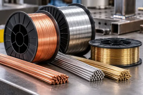
| FC 308L stainless filler | Austenitic stainless weld metal | Carbon-steel E71T-1 will not provide the intended corrosion resistance |
| Complete suffix | Gas, polarity, impact and position | Unstable arc, poor bead shape or an unqualified procedure |
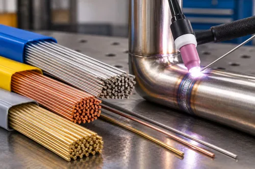
RND Welding Pvt Ltd can help compare a stainless FC 308L option with carbon-steel classifications, but you still need the procedure qualification and service requirements.
Set up the feeder and arc for the wire’s qualified operating range
Real deposition depends on the complete wire-delivery and arc setup, not the power-source nameplate alone. Use the manufacturer parameter chart for the exact wire-and-gas combination and procedure qualification. It should specify wire diameter, wire-feed speed, amperage, voltage, polarity and operating limits.
Gas-shielded wire commonly uses DCEP, while many self-shielded wires use DCEN; reversing polarity can create spatter, poor penetration and an unstable arc.
- Match feeder duty cycle, gun, liner, contact tip and work lead to the selected wire’s sustained current and wire-feed speed. An undersized feeder overheats before the power source reaches its rating.
- Set contact-tip-to-work distance, travel speed and torch angle within the chart’s range. Excessive distance reduces current at the wire tip; excessive travel speed leaves an undersized bead.
- Inspect liner friction and contact tip wear before raising wire-feed speed. Drag or a loose bore causes feeding surges, arc instability and burnback; set burnback time only after mechanical faults are removed.
| Variable | Setup decision | What goes wrong outside the range |
|---|---|---|
| Wire-feed speed | Raise it with amperage | Too low reduces deposition; too high causes stubbing |
| Voltage | Match it to the speed and gas | Too low gives a harsh arc; too high causes spatter and an overly wide bead |
| Travel speed | Hold it steady | Too fast reduces fill; too slow builds excess heat and an oversized bead |
| Gas flow | Use the qualified flow rate | Too little shielding creates porosity; drafts can strip protection from the arc |
Frequently asked questions
How does flux-cored wire put more usable weld metal into a joint?
Continuous wire feeding, high wire-feed speeds and fewer electrode changes increase deposition. The flux core stabilises the arc, protects the pool with slag and helps shape the weld.
What is the difference between gas-shielded and self-shielded FCAW?
Gas-shielded FCAW uses external shielding gas alongside the flux core. Self-shielded FCAW generates shielding from the core, making it suited to different site and production conditions.
Where does high-deposition FCAW save the most time?
It saves the most time on long welds, heavy sections and repeated joints where continuous feeding reduces stoppages for electrode changes.
What should you choose before selecting flux-cored wire diameter?
Choose the wire classification first, then select a diameter that suits the joint, position, equipment and qualified operating range.
How should you set up a flux-cored welding system?
Set the feeder and arc within the wire’s qualified operating range, including its recommended wire-feed speed, voltage, polarity, shielding and contact-tip setup.