A load-bearing weld is reliable only when the steel grade, consumable, joint design, welding variables and inspection records all support the design load. By the end, you will have a practical checklist for reviewing the material certificate, WPS, electrode handling, fit-up, preheat and final inspection before a fabricated member enters service.
Key takeaways
- Define reliability through strength, weld quality, inspection and traceability.
- Match base steel, filler classification and WPS before welding.
- Control hydrogen, preheat and heat input to reduce cracking risk.
- Record inspection results, consumable batches and welder qualifications.
Define reliability before you choose a consumable
Structural welding reliability means you can connect the design load to verified steel strength, qualified welding variables, sound weld geometry, acceptable discontinuities and inspection records. A weld appearance alone proves little: lack of fusion or an undercut toe can remain hidden while reducing static strength or fatigue life in load-bearing steel fabrication.
| Consumable | Strength and control | Decision point |
|---|---|---|
| E7018 | 70 ksi minimum tensile-strength class, with low-hydrogen requirements when supplied and controlled accordingly | Use only when its strength, toughness, position and compatibility match the base steel and design |
| E11018 | 110 ksi minimum tensile-strength class, also requiring controlled hydrogen practice | Use for a qualified higher-strength design; it is not automatically safer or better for ordinary steel |
Ask for evidence that covers these points:
- The mill test certificate identifies the parent grade, thickness, heat number, yield and tensile properties, and chemistry or carbon equivalent. For IS 2062 E250 E350 steel, confirm the exact grade rather than relying on a supplier’s verbal description.
- The qualified WPS names the process, filler classification, diameter, amperage, voltage, travel speed, preheat, interpass temperature, heat input and any post-weld heat treatment. If production falls outside a prequalified code limit, procedure qualification testing is required.
- Traceability links the consumable lot, storage and issue records, WPS, welder, weld location and inspection results. Visual inspection plus specified NDT and acceptance criteria then provide evidence that the completed weld meets its design basis.
Match the base steel, filler classification and WPS
Use a qualified welding procedure specification (WPS) that covers the actual steel grade, thickness, joint and service conditions; do not choose an electrode by strength alone. Confirm the mill test certificate, grade designation such as IS 2062 E250 or E350, plate thickness and carbon equivalent before approving the procedure.
1. Check the governing code, such as AWS D1.1/D1.1M, for the permitted base-metal group, joint detail and qualification route. A change to an essential variable can invalidate an otherwise experienced welder’s procedure.
2. Match the WPS to the work. It must identify the process, electrode classification and diameter, welding position, amperage, voltage, travel speed, heat input, minimum preheat, maximum interpass temperature and any post-weld heat treatment.
3. Specify toughness as well as strength. A weld that meets tensile requirements can still fail a Charpy impact requirement in cold service. Check the electrode’s hydrogen designation, impact-test results and compatibility with the parent steel.
4. Assess restraint and through-thickness loading separately. A stronger filler will not prevent lamellar tearing in a restrained T-joint; use suitable plate quality, joint geometry, reduced restraint, buttering or a controlled sequence when the design demands it.
E7018 vs E11018 | Strength and use | Selection decision E7018 | 70 ksi minimum tensile strength; low-hydrogen, all-position electrode | Use when the qualified WPS and base steel require this strength level.
E11018 | 110 ksi minimum tensile strength; low-hydrogen, all-position electrode | Use only when the WPS, toughness requirement and base steel support the higher-strength weld metal. Higher strength is not automatically safer: it can reduce ductility, complicate cracking control or exceed the compatible steel-and-procedure combination.
Control hydrogen, preheat and heat input at the joint
Delayed cracking can appear hours after welding, even when the bead looks sound. It develops when diffusible hydrogen enters a susceptible microstructure under tensile restraint or residual stress, so dry consumables alone cannot make a joint reliable.
Use these controls at the joint:
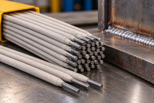
- Store low-hydrogen electrodes in sealed packaging until issue, then hold them in the manufacturer’s specified heated oven. Follow the stated exposure limit; perform electrode rebaking at the specified temperature and time when moisture pickup exceeds that limit. Discard electrodes with damaged coatings.
- Measure the preheat temperature on the thicker member beside the joint, not in the torch flame. Reach the WPS minimum before striking the arc and keep the joint warm through root and fill passes.
- Control interpass temperature separately from initial preheat. A value below the WPS minimum accelerates cooling and raises cracking risk; a value above its maximum can coarsen grains and reduce toughness.
- Keep current, arc voltage and travel speed within the qualified WPS range. Excessive heat input can lower toughness and alter strength, while insufficient heat input can produce rapid cooling, incomplete fusion or an under-sized weld.
Clean moisture, oil and heavy rust from the joint before welding, and do not increase restraint by forcing misaligned parts together. AWS D1.1/D1.1M limits preheat, interpass temperature and heat input for each qualified procedure; changing an essential variable requires procedure qualification rather than an informal adjustment.
Make joint preparation and welding sequence part of the design
Design the joint so the welder can achieve complete fusion without forcing excessive restraint into the connection. Bevel angle, root face, root gap and alignment control penetration, effective throat and final weld profile; adding filler metal cannot reliably correct poor weld joint preparation.
1. Set the bevel geometry, root gap and root face on the drawing and WPS. A narrow bevel or excessive root face can cause incomplete penetration; an excessive root gap can cause burn-through, oversized welds and distortion. State the fit-up tolerance for root opening, bevel angle, high-low mismatch and alignment, then measure it before welding.
2. Use sound, qualified tack welds at the specified spacing and length. A cracked tack becomes a defect in the finished weld, while oversized or poorly placed tacks lock in misalignment and increase restraint. Remove defective tacks instead of welding over them.
3. Choose the welding position and welding sequence together. Plan starts, stops and pass placement to balance shrinkage, limit angular distortion and keep the arc accessible for fusion at both toes and the root. Alternate sides or weld from the least restrained area when the joint permits it.
For highly restrained T- and corner joints, review lamellar-tearing risk before fabrication. Through-thickness material, reduced restraint, buttering or a revised sequence can protect the plate; a stronger electrode cannot. Smooth transitions and controlled starts, stops and toes also reduce fatigue stress raisers, so static weld strength alone does not establish load capacity.
Verify the finished weld and preserve its traceability
A completed weld passes structural weld inspection only when its measured condition meets the drawing, WPS and governing construction code. Visual testing (VT) checks weld size, profile, undercut, overlap, arc strikes, surface cracks, exposed porosity and dimensional errors; it cannot prove internal soundness.
Fatigue acceptance also depends on toe geometry, starts and stops, attachment ends and the specified detail category and stress range.
| Method | Detects | Limitation |
|---|---|---|
| Visual testing (VT) | Surface cracks, undercut, overlap, profile and size errors | Cannot verify internal fusion or buried discontinuities |
| Ultrasonic testing (UT) | Internal planar flaws and lack of fusion in suitable thicknesses | Needs qualified operators, calibrated equipment and access |
| Radiographic testing (RT) | Volumetric porosity, inclusions and some internal fusion defects | Less effective for tight planar flaws and requires radiation controls |
Preserve evidence that lets you isolate a bad lot or process change instead of rejecting an entire frame:
- File the approved WPS, welder identification, weld map, joint number, inspection date, method, equipment calibration and acceptance result.
- Link each weld to the electrode or wire classification, lot or heat number, mill certificate, storage and issue record.
- Record repair locations, excavation method, re-welding and repeat inspection; a later pass does not erase the original failure.
- Ask RND Welding Pvt Ltd to connect supplied consumable lot certificates with your purchase and issue records before fabrication starts.
Related product
 | Welding Electrodes Material Mild Steel Length 350 mm Size 3.15 mm Brand Lincoln Model Name/Number Conarc 80 Diameter 3.2mm Established in the year of 2018, RND Welding... View product → |
Frequently asked questions
What defines reliability in load-bearing structural welding?
Reliability connects the design load to verified steel strength, qualified welding variables, sound weld geometry, acceptable discontinuities and inspection records.
How do you match filler metal to structural steel?
Confirm the base-steel grade, strength requirements, service conditions and applicable filler classification, then use a WPS qualified for that combination.
Why do hydrogen, preheat and heat input matter?
Hydrogen control and suitable preheat reduce cracking risk, while controlled heat input helps manage weld strength, distortion and the heat-affected zone.
How do you verify and preserve weld traceability?
Use the specified visual and non-destructive examinations, record results, and link welds to the WPS, welder, consumable batch and inspection documentation.